Raspberry Pi Table Tennis Scorer
This is a post about how I built/programmed a Raspberry Pi to turn it into a simple table tennis scoring device.
Rules of table tennis
In case anybody is not familiar. Table tennis can be played in singles or doubles. There are two teams (in singles, each team is just one person.) I’m calling the teams red and white, mainly because that’s the colours of the LEDs and buttons that I had. One of the teams gets to serve, I have let that be chosen randomly in my device. Serve switches between the team every two points, irrespective of who wins. Once a team has at least 11 points (21 for doubles) and is at least two points ahead of the opposition, they have won the game.
What my device does
There is no graphical interface. The interface is just two lights and three buttons. Using those buttons I had to achieve:
- reset the game;
- register points for the red team;
- register points for the white team;
- help the players know when their button press has registered, so they don’t keep trying;
- tell the players when the game is over; and
- tell the players who is supposed to be serving.
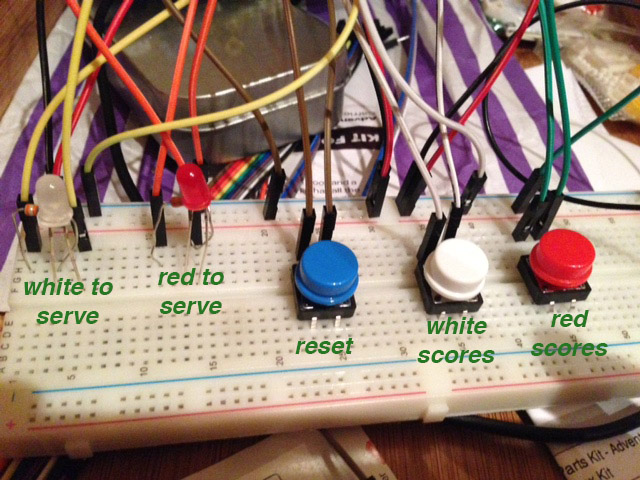
Not too much, but I count maybe 6 things to do with 5 components. Here’s how it’s laid out:

The text is green tells you what the light or button does, it’s not really there on the circuit. This picture is augmented reality.
Here’s a short video of how it works:
I’m particularly proud of the little blink that happens after you register a score. Without a little feedback it would be too easy to inadvertently register the same point twice. This is so true of complex GUIs as well. Clear visual feedback is important. Having the colours of the buttons match the lights is fortuitous (I just got a kit, so I was lucky with the colours) but helpful.
Circuit design
I’m not very familiar with doing circuits so this was the hardest part for me. The many GPIO pins on the RPi made it possible for me to play to my strengths though: I didn’t have to design a complicated circuit with logic gates and storage. Instead all the storage and logic was in the Python code. Instead you can essentially set or get the signals on the pins using Python code. Hence, I basically just had to wire up the 2 lights and 3 buttons to 5 different IO pins.
I got my buttons as part of this Adventures in Raspberry Pi Kit. I don’t have the book. The parts just looked like a good selection so I chose this kit.
There is a good set of diagrams of the GPIO pins on the RPi here.
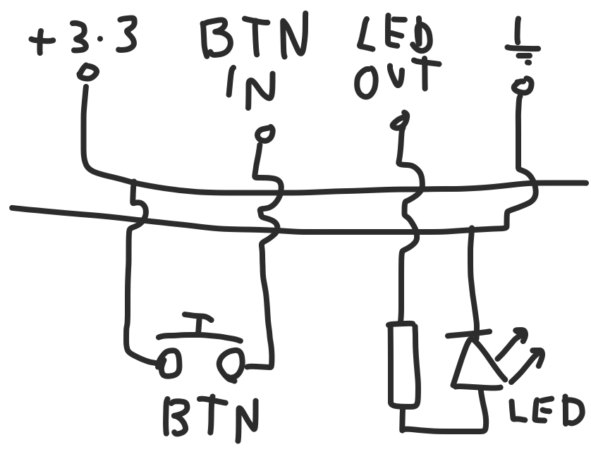
I couldn’t be bothered to draw a proper circuit diagram, so you’re going to have to make do with this hand/Adobe Draw drawn monstrosity:

The first pattern here is that I had to wire the button up to the 3.3V output port on one side and on the other side into one of the GPIO ports used an an input. Apparently you’re supposed to use a resistor or two in here, but I didn’t have any and it worked for me. But it could just as easily have blown up so please be careful.
The second pattern is to connect the LED up to a GPIO port used as an output. I did put a resistor in here, I think because I was following this guide the recommended that. I don’t know why that was necessary. I could easily have fried the board I suppose, but the components all came as a kit so presumably the LED and resistors were in some way “matched”.
Software
The software is available to view at my github.
I’m not going to go through every line. I’m basically going to completely ignore the file “tt.py” which just contains an implementation of the table tennis rules in Python. It’s very simple.
The file main.py is where the action is. I’m just going to go through it line by line explaining what it’s for and what it does. I’ll paste the code in first and then describe it immediately after.
1
2
3
4
5
6
RESET_IN = 19   # GPIO10
A_SCORE_IN = 11 # GPIO17
B_SCORE_IN = 12 # GPIO18

A_SERVES_OUT = 23 # GPIO11
B_SERVES_OUT = 24 # GPIO08
Defining port numbers for each input and output.
1
2
3
4
5
6
7
8
9
10
11
12
def setup_gpio():
	GPIO.setmode(GPIO.BOARD)

	GPIO.setup(RESET_IN, GPIO.IN, pull_up_down=GPIO.PUD_DOWN)
	GPIO.setup(A_SCORE_IN, GPIO.IN, pull_up_down=GPIO.PUD_DOWN)
	GPIO.setup(B_SCORE_IN, GPIO.IN, pull_up_down=GPIO.PUD_DOWN)

	GPIO.setup(A_SERVES_OUT, GPIO.OUT)
	GPIO.setup(B_SERVES_OUT, GPIO.OUT)

def teardown_gpio():
	GPIO.cleanup()
Setup and teardown code for the 5 input or output ports.
1
2
3
4
5
6
7
8
9
def pressed(pin):
	pressed = GPIO.input(pin)
	if not pressed:
		return False
	else:
		while GPIO.input(pin):
			time.sleep(0.01)
		time.sleep(0.01)
		return True
A function to test whether an input is on. If the input is 0, simply return False because it’s not on. But if it is on we have to wait until it turns off before returning True. That is because my code is implemented as a busy loop and we don’t want to register the button press twice in two different loops.
It’s probably worth mentioning that buttons don’t always give a completely clean output. It is possible that somebody will press it and let go and the input would register a pattern like 1,1,1,1,1,0,0,1,0,0,… The final 1 is a little physical or electronic “bounce” that might potentially look like an additional button press if you’re unlucky. AFAIK the solution is to put a little sleep after the button output goes to 0, to wait out any potential jitters.
1
2
3
4
5
6
7
8
9
10
11
12
13
14
15
def turn_on(pin):
	GPIO.output(pin, 1)

def flash_until(pin_to_flash, pin_to_stop_on):
	while not pressed(RESET_IN):
		time.sleep(0.5)
		turn_on(pin_to_flash)
		time.sleep(0.5)
		turn_off(pin_to_flash)

def momentary_blink(pin):
	turn_off(pin)
	time.sleep(0.05)
	turn_on(pin)
	time.sleep(0.05)
A little bag of input and output convenience methods. I think they’re all pretty self explanatory. Now the main loop that brings the parts together:
1
2
3
4
5
6
7
8
9
10
11
12
13
14
15
16
17
18
19
20
21
22
23
24
25
26
27
28
29
30
31
32
33
def main():
	setup_gpio()

	game = tt.Game.make_singles_game(random_bool())
	while True:
		if pressed(A_SCORE_IN):
			momentary_blink(A_SERVES_OUT)
			game.scores(game.get_A())
		elif pressed(B_SCORE_IN):
			momentary_blink(B_SERVES_OUT)
			game.scores(game.get_B())

		reset = False
		if game.has_won(game.get_A()):
			light_set(B_SERVES_OUT, False)
			flash_until(A_SERVES_OUT, RESET_IN)
			reset = True
		elif game.has_won(game.get_B()):
			light_set(A_SERVES_OUT, False)
			flash_until(B_SERVES_OUT, RESET_IN)
			reset = True
		elif pressed(RESET_IN):
			reset = True

		if reset:
			game = tt.Game.make_singles_game(random_bool())

		light_set(A_SERVES_OUT, game.to_serve(game.get_A()))
		light_set(B_SERVES_OUT, game.to_serve(game.get_B()))

		pass

	teardown_gpio()
The logic was fairly clear because of all the helper functions I wrote and the fact that the table tennis logic was hidden away in another class. I possibly didn’t take the MVC pattern far enough though. Conceivably I could have encapsulated the circuit model in another class and this would have only been glue code between the table tennis class and circuit class.
Possible improvements
- Use an event driven input model, to avoid the busy loop.
- Add button and a light for doubles mode.
- Add the LED display I’ve got to show the scores for each player.
Music
Finish with closing credits: